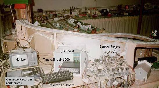

The relays on the I/O board activate separate relays
which have
their own power supply. The relays on the I/O board get their
power
from the computer. A relay is activated by POKING the appropriate
value. All 8 relays can be activated by POKING 255 (128+64+32+16+8+4+2+1).
The inputs are done by way of a small light bulb
causing the photo
resistor to ground the I/O board's input, which indicates to the computer
that a particular input is "on" by way of a PEEK 16381. There is no
physical
connection here to the computer, just the light activates the input.
The
photo resistor is wired to the I/O board's input. However, in
the case
of the output, there is a physical connection to the computer by way
of
the output board's small normally open relays, however there isn't
an
actual electrical connection to the computer's circuitry. (In
my case,
an insulated rail or magnetic reed switch turns on a small light bulb
to
activate an input.)
The following T/S BASIC program example will stop
the train, throw a
turnout's switch, back the train into the station and turn on a sound
effects tape.
10 LET X = 16382
20 LET Y = 16381
90 LET B=PEEK Y
100 IF INT(B/2) <> INT ((B/2) + 0.5) THEN
GOTO 200
110 GOTO 90
200 POKE X, 1
210 PAUSE 40
220 POKE X, 0
230 PAUSE 40
235 POKE X, 2
236 PAUSE 10
237 POKE X, 0
238 PAUSE 10
240 POKE X, 1
250 PAUSE 40
260 POKE X, 0
300 LET B=PEEK Y
301 IF INT (B/4) <> INT ((B/4) + 0.5) THEN GOTO 315
302 GOTO 300
315 POKE X, 1
320 PAUSE 40
330 POKE X, 4
POKE X,1 activates relay #1, breaking track
current.
POKE X, 2 activates relay # 2, activating
the turnout's solenoid.
POKE X, 4 turns on a tape player with
train station sound effects.
Lines 90 - 110 make a loop waiting for the train to hit the track section
that grounds input # 1. The input byte is unpacked by line 100.
Only
input # 1 is being checked here. When the train reaches this section,
the loop is broken and line 200 breaks the current to the track, causing
the train to stop dead.
Line 220, after a pause, re-applies current to the track, causing the
train to be in neutral. There is a reversing unit in the engine
that
cycles forward-neutral-reverse-neutral, etc., every time current is
broken then re-applied. In the case of a train where polarity
is
reversed for reverse movement, then an additional relay is used to
change polarity.
Line 235 activates the turnout's switch machine momentarily.
Line 240 removes current a second time to the track.
Line 260 re-applies current to the track and train reverses direction.
Line 300 - 302 waits for the train to hit the section of track near
the
r/r station, activating input # 2. Only input #2 is being checked here.
Line 315 breaks track current, causing train to stop.
Line 330 turns on sound effects by way of POKE 4, and applies current
to
the rails, with train now in neutral with full interior illumination.
To activate multiple relays, simply add up
the corresponding
numbers. For example, if you want sound effects while track is
powered,
line 200 would be POKE X, 5 (1 for relay #1, and 4 for relay # 3).
See the
input/output table below. Simply add up the corresponding number to
activate
relays. POKE X, 36 would activate relays #6 (POKE 32) and # 3
(POKE
4). Unpacking the input byte is a little harder. Notice
line 100.
Simply change the value that B is divided by to check for a particular
input to be "on." To check for input #8, any number greater than
127 in
PEEK 16381 would indicate input # 8 is "on." In my case, I only
check
for one input at a time, so I don't need to unpack the whole input
byte,
just one single bit.
In the third diagram, notice how
a second device can be
activated by one relay. It is best to use 4PDT relays if possible.
A relay can do double (even triple) duty by having different
track sections wired to just one relay, and its function would change
depending on where the train may be at any given time. (See diagram
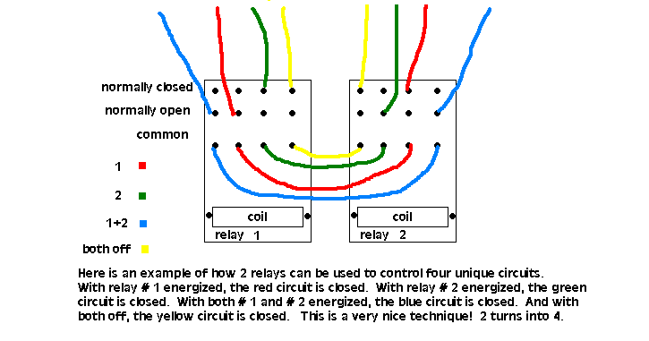
below for another way to get more control from relays.)
Above is not the actual T/S BASIC
program, but rather a simplified
version for clarity.
